Using Handshake Outputs As Power Sources

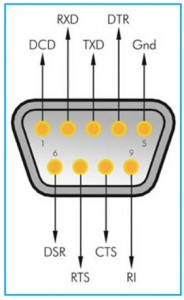
Fig.1. Connection details for a PC 9-pin serial port. A 9-pin female D connector is needed to make connections to the port
The two previous Interface articles considered the use of RS232C handshake lines as a means of controlling user addons. The RS232C serial port can be a standard type or it can be provided by a USB-to-serial converter.
Once installed properly and integrated into the Windows operating system, a USB-toserial converter is used in the same way as a normal serial port, and it is treated in exactly the same way when writing the control software. As explained in the previous Interface articles, two handshake outputs (DTR and RTS) are under direct software control when using the SerialPort component of Visual BASIC 2008.
Unfortunately, no other lines can be controlled directly, and there is no easy way of controlling the Transmitted Data output line on a simple true/false basis. Direct control of this line might be possible using more roundabout methods, but it does not appear to be a feature of the SerialPort component.
There is an even bigger omission in that it is not possible to directly read any of the input lines either. This is a pity, as it would provide a quick and easy means of providing basic information from add-on devices. Instead, all information has to enter the port as normal asynchronous serial data. Since hardware handshaking is not normally required, due to the relatively slow data rates involved, the handshake inputs are therefore superfluous.
Supply difficulties
One problem in using a serial port with user add-ons is that there is no supply output of any kind. When using a USB-to-serial converter there is a +5V supply output on the USB port, but this is not available from the serial port.
It is likely that there is a fair amount of unused supply current available from the USB port, but it could be difficult to find a neat way of accessing it. In fact, it would almost certainly be easier to use a second USB port to provide power for the main circuit. Other options are to use a battery supply, or a battery eliminator.
Another possibility is to use the handshake outputs as power sources. Of course, this is only a practical proposition if they are not being used for other purposes, which they will probably not be if the port is only being used to read data, or the transmitted data is being sent in asynchronous form via the Transmitted Data output. It will not be possible if the handshake outputs are being used to send synchronous data using the method outlined in the previous Interface article.
Of course, the amount of current that can be drawn from an RS232C handshake output is not very great. The nominal output potentials are ±12V, but the actual voltage under no loading varies enormously. A typical PC serial port provides unloaded output potentials that are slightly higher than these nominal levels, while a USB-to-serial converter is likely to fall a couple of volts short of them.
Presumably, the USB converters have voltage doubler circuits that give nominal output levels of ±10V from the 5V supply of the USB port. Many laptop PCs have unloaded output potentials of around ±5V, which is two volts higher than the bare minimum needed to conform to the RS232C standard, but it makes them of little use as supply outputs.
Current limiting on all outputs is a requirement of the RS232C standard, and this is done to prevent any damage if two outputs should be connected together by accident. This is unfortunate in the current context, as it severely limits the maximum supply current that can be drawn from each handshake output.
Short circuiting a handshake output to ground is unlikely to produce a current flow of much more than about 10 milliamps, and in some cases the short-circuit current is a bit less than this. The output current is usually limited by a series resistor rather than some form of semiconductor limiting circuit, and the practical consequence of this is that the output voltage starts to fall as soon as you start to draw any current.
Balanced view
Because of the series resistor, it is usually necessary to add a voltage regulator in order to use a handshake line as a power source. One possible exception is where it is necessary to have dual balanced supplies in order to power an analogue signal processing circuit based on operational amplifiers. With this type of circuit it is not normally necessary for the supply lines to be well stabilised, noisefree, or accurately balanced. Operational amplifiers and the circuits in which they operate are normally designed to be largely oblivious to any irregularities in the supply lines.
On the face of it, no circuitry is needed other than the usual supply decoupling capacitors. In practice, this is fine, provided the two handshake outputs are set to the correct states prior to the add-on being connected to the serial port.

Fig.2. A simple circuit that provides dual balanced supplies from the two handshake outputs of an RS232C port. The DTR and RTS lines must be set to true and false respectively
Since it is likely that the add-on will often be connected to the computer at switch-on, and the correct starting levels for the two output lines are unlikely to be correct by default, it is advisable to include protection diodes (see Fig.2) to ensure that the circuit cannot be fed with supplies of the wrong polarity. The voltage drop of about 0.6V or so through each diode is unwelcome, but is unlikely to be of any great significance in practice. The voltage drop could be minimised by using Schottky diodes instead of an ordinary silicon type. Each output voltage would then be reduced by about 0.2V.
The supply voltages obtained are something that is dependent on the particular RS232C port in use, and the current consumption of the circuit. Using a circuit based on two or three ordinary operational amplifiers, it is likely that the actual supply potentials would only be about half their nominal levels of ±12V.
This might be sufficient, but where possible it is probably best to use low current consumption operational amplifiers, such as the TL061CP. Four of these will typically consume less than one milliamp and place minimal loading on the supply lines. Typical supply potentials of around ±8V to ±10V could then be achieved.
Drop-out generation

Fig.3. This circuit provides stabilised supplies of plus and minus 5-volts. It is necessary to use LDO regulators in order to obtain worthwhile maximum output currents
It is possible to obtain stable 5V supplies of either polarity, or both, but the maximum output current will still be quite low even at this reduced output voltage. Also, it is necessary to use something other than ‘bog standard’ voltage regulators in order to obtain a worthwhile output current. All that is needed in order to obtain a regulated 5V supply is a low-power regulator chip added at each handshake output. In the example of Fig.3, the two handshake outputs are fed to separate regulator chips, with IC1 providing a positive supply, while IC2 provides a negative one. Of course, as with all the supply circuits featured here, the two handshake lines must be set to the appropriate output levels in order to get the circuit to function properly.
Ordinary regulator chips will not provide particularly good results in this application, with the supply probably sagging below 5V if more than a milliamp or two of output current is drawn. Clearly, the limitations of the power sources prevent very much more than this from being obtained, but the maximum output current is still less than one would probably expect.
One reason for the apparent shortfall is that the regulator chip itself requires a small but significant supply current. The actual current consumed is quite low, at around four milliamps, but the available output current is reduced by this amount.
The other cause of the problem is the drop-out voltage of the regulator, which is the minimum input voltage needed in order to maintain the output at 5V. For a small 5V regulator this potential is normally about 7V to 8V. The regulator ceases to function properly when the handshake line is pulled down to this level, and not when it reaches 5V. This reduces the maximum available output current by a significant amount.
The solution to the problem is to use a modern regulator chip that has reduced current consumption and a low drop-out voltage. In component catalogues these are usually referred to simply as LDO (low dropout) regulators.
As an example of one of these chips, the LE50CZ positive voltage regulator has a dropout potential that is typically just 0.2V higher than the output voltage, together with a typical current consumption of just 0.5mA. Using a modern regulator chip such as this, it should be possible to obtain a properly regulated output potential with output currents of up to about 7mA or 8mA with most RS232C ports.
Doubling up

Fig.4. Using two handshake outputs in parallel enables a higher maximum output current to be achieved
While an output current of this order is still very low, it is actually sufficient to power many modern circuits. However, it is possible to obtain higher output currents provided only a single supply is required. The basic technique is to drive the voltage regulator from two handshake outputs, as in Fig.4. In this case, the two outputs must both be set at +12V (true).
The two diodes (D1 and D2) form a simple mixer that enables the two outputs to drive the regulator chip, but prevents one line from driving any output current into the other one. The mixing process requires a series resistor in each handshake output line, but there is no need to include these in the circuit. The builtin current limiting of each handshake line effectively provides this resistance.
Using two handshake lines, Schottky diodes, and a good LDO regulator it should be possible to obtain something in the region of 12mA to 15mA from most serial ports. This is still fairly low, but it is sufficient to drive many modern circuits. After all, there are plenty of modern logic devices and analogue circuits that have minute power consumptions.
Driving a few LED indicator lights should be no problem, since it is now possible to obtain devices that require a supply current of only one or two milliamps for effective operation. Being realistic about things, it would not be possible to accommodate higher current devices such as most relays, filament bulbs, and the like.
There is a third output on a serial port in the form of the Transmitted Data output (pin 3). This can be used as a supply output if it is not being used to output data, but as explained previously, there is no simple way of directly controlling the output level of this line.
It normally goes to –12V under standby conditions, so it can be used to provide a negative supply. Unfortunately, it cannot be used to provide a positive supply, or to boost the other two lines and provide an augmented +5V supply with output currents of up to around 20mA or so.
