The Approaches to Implement the Control Channel
It is worth noticing that the number of connections required between these modules and head units in vehicles multiplies increased as more and more displays, cameras, and sensors used in it. Therefore, it will increase both cost and weight and impacts production assembly cost and reliability concerns. What’s more, it needs more data connection to control and update the cameras and displays as the number of video links grows. Using a control channel, we can automatically adjust the brightness and back lighting settings. The key point is that control data is travelling against the direction of the video data flow.
There is a standard approach to implement such a control channel. It uses separate control wires in parallel from camera to head unit or from head unit to display to the video link. While the design challenge is to make more efficient use of existing wires and connectors for the video, control, and data signals. This isn’t a suggested application for collision avoidance systems, but is analogous to the challenge of providing a control path that flows in the opposite direction of the main high-speed video data. As previously noted, the ideal solution would also provide this control channel using only existing wiring and can, in fact, be implemented in a number of ways.
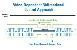
Displays tend to use the video blanking period inherited from the old CRT days to send non-video data. CRT displays required blanking periods added at the end of every active video line and field to allow for the ‘fly-back’ time of the beam. Over the years, creative video system designers have used the blanking interval to transmit information such as closed captioning text or video time code information. Newer display technologies, such as LCD, have retained the blanking periods although they are no longer truly necessary. Below shows a scheme that uses video blanking periods to send control information, however, the amount of data that can be transmitted is limited to the length and frequency of the blanking period. This is especially limiting if only the vertical blanking period is used in a system supporting a typical frame rate of 30Hz. There is also a trend in the industry to significantly diminish this wasted overhead as it has a direct impact on both power consumption and pixel clock rate.
A further disadvantage of this approach is that the control data must be queued for transmission.
The resulting delay introduces a non-deterministic latency that can be unacceptable for many applications, such as collision avoidance systems where response times of micro-seconds are required. This is also restrictive for applications where the precise timing of the control data has relevance, for example, attempting to synchronize multi-camera systems using this approach would be a challenge.
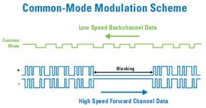
Another approach, shown in the below figure, makes use of the differential nature of the signal used for the primary video channel. Control data can effectively be coupled into the cable as a common-mode modulation of the digitized video signal; however, this presents a fundamental EMI issue. Automotive applications enforce very strict EMC standards to avoid interference between electronic subsystems.


